Documentation For Design, Simulation and Implementation of a Secure LAN Infrastructure for a Betting Shop (Example: Bet9ja)
1. Project Overview
Project Title: Design, Simulation and Implementation of a Secure LAN for a Small Betting Shop (Bet9ja-style)
Project Description: This project involves the design and simulation of a Local Area Network (LAN) for a small betting shop. The network will include multiple betting sections, an admin area, a server, and an isolated guest Wi-Fi network.
- Security: Prevent unauthorized access between betting terminals, admin, and guests.
- Manageability: Easy to configure and maintain.
- Scalability: Ability to add more devices in future.
- Reliability: Ensure stable network operations with proper cabling and UPS protection.
2. Network Requirements
2.1 Functional Requirements
| Area |
Devices |
| Section A |
6 PCs, 6 thermal printers |
| Section B |
6 PCs, 6 thermal printers |
| Admin |
2 PCs, 2 printers, 1 server |
| Wireless |
Guest Wi-Fi (isolated) |
2.2 Non-Functional Requirements
- High availability
- Secure data transmission
- Guest network isolation
- Easy expansion and maintenance
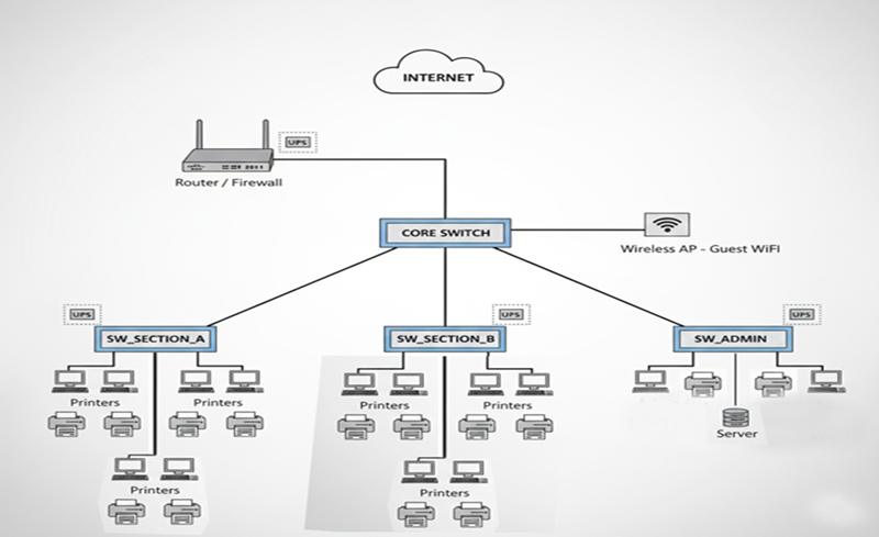
3. Physical Network Design
3.1 Physical Topology
The network uses a hierarchical star topology:
3.2 Hardware Components
| Device |
Quantity |
Purpose |
| Router / Firewall |
1 |
Internet access, VLAN routing |
| Core Switch |
1 |
Central device connecting all switches |
| Access Switches |
3 |
Connect PCs and printers |
| PCs |
14 |
Betting terminals and admin PCs |
| Printers |
14 |
Thermal printers for betting slips and admin printers |
| Server |
1 |
Betting application and data storage |
| Wireless AP |
1 |
Guest Wi-Fi |
| UPS |
Multiple |
Power backup for critical devices |
| Ethernet Cables |
As required |
Network connectivity |
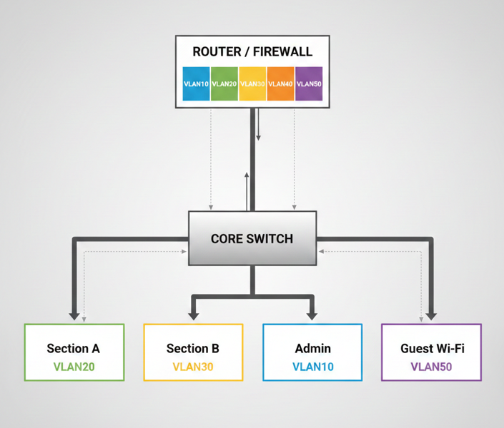
4. Logical Network Design
4.1 VLAN Design
| VLAN ID |
Name |
Devices |
| 10 |
ADMIN |
Admin PCs + Server |
| 20 |
SECTION_A |
Section A PCs |
| 30 |
SECTION_B |
Section B PCs |
| 40 |
PRINTERS |
All printers |
| 50 |
GUEST_WIFI |
Guest Wireless users |
4.2 IP Addressing Plan
| VLAN |
Network Address |
Gateway |
| 10 |
10.10.10.0 /24 |
10.10.10.1 |
| 20 |
10.10.20.0 /24 |
10.10.20.1 |
| 30 |
10.10.30.0 /24 |
10.10.30.1 |
| 40 |
10.10.40.0 /24 |
10.10.40.1 |
| 50 |
192.168.50.0 /24 |
192.168.50.1 |
4.3 Logical Network Diagram
5. Implementation in Cisco Packet Tracer
5.1 Device Selection
- Router: ISR 2911
- Switches: Cisco 2960 (Core & Access)
- PCs: Generic PC
- Printers: Generic Printer
- Server: Generic Server
- Wireless AP: Wireless Router (AP mode)
5.2 Cabling Guidelines
| Connection | Cable Type |
|---|
| PC → Switch | Copper Straight-Through |
| Printer → Switch | Copper Straight-Through |
| Server → Switch | Copper Straight-Through |
| Switch → Switch | Copper Straight-Through |
| Switch → Router | Copper Straight-Through |
| AP → Switch | Copper Straight-Through |
5.3 VLAN Configuration Example
enable
configure terminal
vlan 10
name ADMIN
vlan 20
name SECTION_A
vlan 30
name SECTION_B
vlan 40
name PRINTERS
vlan 50
name GUEST_WIFI
exit
5.4 Router-on-a-Stick Configuration
interface g0/0
no shutdown

interface g0/0.10
encapsulation dot1Q 10
ip address 10.10.10.1 255.255.255.0

interface g0/0.20
encapsulation dot1Q 20
ip address 10.10.20.1 255.255.255.0

interface g0/0.30
encapsulation dot1Q 30
ip address 10.10.30.1 255.255.255.0

interface g0/0.40
encapsulation dot1Q 40
ip address 10.10.40.1 255.255.255.0

interface g0/0.50
encapsulation dot1Q 50
ip address 192.168.50.1 255.255.255.0
5.5 DHCP Example
ip dhcp pool ADMIN
network 10.10.10.0 255.255.255.0
default-router 10.10.10.1

ip dhcp pool SECTION_A
network 10.10.20.0 255.255.255.0
default-router 10.10.20.1
5.6 Wireless Configuration
- SSID: BetShop-FreeWiFi
- VLAN: 50
- Security: WPA2
5.7 Testing
- Same VLAN devices → ping success
- Different VLAN devices (restricted) → ping fail
- Guest Wi-Fi → cannot access internal network
6. Security & Best Practices
- VLAN segmentation isolates traffic
- Guest Wi-Fi cannot access internal network
- Admin PCs have full access to server
- UPS for critical devices
- Printer ports accessible only by relevant PCs
- Regular backups for server
7. Conclusion
This project demonstrates a secure, reliable, and scalable LAN design for a small betting shop. The network uses VLAN segmentation, router-on-a-stick inter-VLAN routing, DHCP for automatic IP assignment, and an isolated guest Wi-Fi network, ensuring security and easy management. It is ready for real-world deployment or simulation in Cisco Packet Tracer.